Linksys router password is always "admin". Have you ever try to change the password? Nope? I recommend you to change it. All the Linksys networking devices has default password "admin". If you haven't try to change the password it may happen that someone can access the linksys router's setup page and change the setup without even noticing it. They can connect wirelessly to your router and they can configure the router the way they want it.
So, how do we change the linksys router password? It's just simple! It will take you 3 minutes to do that. Just follow this steps:
Access the router's setup page. Don't know how to access router's setup page?Go to my article : HOW TO ACCESS LINKSYS ROUTER'S SETUP PAGE?Go to "ADMINISTRATION" tab.Go to "MANAGEMENT" sub-tab.On the "ROUTER PASSWORD" textbox, type your own or your preferred password. This will serve as your router's password from now on.On the "RE-ENTER TO CONFIRM" textbox, type again our own or your preferred password.And, click "SAVE SETTINGS" button.
View the original article here
Saturday, December 25, 2010
HOW TO CONNECT YOUR LINKSYS ROUTER to your MODEM?
By aventus · June 18, 2009 · · 2,388 Views You have just bought a linksys router(e.g. WRT54G, WRT54GS,BEFSR41, etc.) and you want it to connect to your modem. How can you do that? It's simple! Connecting linksys router to your modem will just take 2 minutes of your time! Just follow this steps: Using an Ethernet cable, connect one end to the Ethernet port of your modem and the other end to the "Internet"/WAN of the Linksys router. (NOTE:Look at the back of the router, there is a label named "INTERNET" port.)Using another Ethernet cable, connect one end to one of the Ethernet/LAN ports of the Linksys router and the other end to the Ethernet/LAN port of your PC. (NOTE: At the back of the Linksys router, there are numbered ports like 1,2,3,4. Those are the Ethernet ports)Make sure the power adapter of your router is plugged to a power outlet.Filed in: Help
Tagged with: technology, gadgets
To post comments, please log in or register.
Tagged with: technology, gadgets
To post comments, please log in or register.
CHECK IF SOMEONE IS ACCESSING MY INTERNET CONNECTION
All of the laptops manufactured these days have built-in wireless adapter/wi-fi. Most of the people these days have their own wireless adapter or router connected to their desktops. Don't you know that they can connect to someone else's network wirelessly?If you do have wireless router, gateway or other wireless networking devices (ex. WRT54G-LINKSYS wireless router or WCG200 for gateway), don't you know that you can connect 21 wireless PCs to it? And if your router is not secured, don't you know that someone in your area having built-in Wi-Fi on their PCs can connect to your own network without even noticing it. Maybe you'll find one day that you are having slow internet connection because of too many users doing multiple applications in your network. Or if you subscribe for fast internet connection to your ISP, maybe you'll might not even notice that you're not the only one connected to your internet.Do you have Linksys router? You can check it on your router's setup page!Here's the steps to check if there are other computers that you don't own are connected to your Linksys router without your permission.1. Check your PC's/PCs MAC address. Write it down on a piece of paper. How to do that? Check my article: "HOW TO CHECK MY COMPUTER'S MAC ADDRESS".NOTE: In Windows 2000 or XP, MAC address is the same with "Physical Address". In Windows 98 or lower version, it is called "Network Address".2. Access router's set-up page. If you do have Linksys router and don't know how to do that, go to my article: "HOW TO ACCESS LINKSYS ROUTER'S SET-UP PAGE".3. Go to "Wireless" tab.4. Under "Wireless" tab, go to "Wireless Network access" or "Wireless MAC Filter".5. Click "Edit MAC Filter List"6. You will see "Wireless MAC Client" window. On this window, you will see "ACTIVE PC" option. Listed here is the MAC Address connected to your router. Now, match the MAC address of your PC from the MAC addresses listed there. Did you see MAC address that does not belong to your PC/PCs? That may be someone else's PC. Then, try to enable MAC filter. Do you know how to enable MAC filter? Go to my article: "HOW TO SETUP WIRELESS MAC FILTER ON A LINKSYS ROUTER?".
Easy WayTO TROUBLESHOOT LINKSYS ROUTERS FOR DSL ISP?
Many people experienced problem in their router after their router was turned off. Upon turning on the router, the computer, and open your browser, what you've got is "Page Cannot Be Displayed" message.
 What you do is you try to type again the web address (URL) . But upon trying that for several times, you tried to visit another site, and what you get is the same screen, "Page Cannot be Displayed". Oh no, you don't have internet connection!
 What most people do after seeing this message is they contact their ISP (Internet Service Provider). That a great idea! But contacting ISP is not that too easy! You are on queue of thousands of people trying to reach the ISP's technical support dept.! You wait for 30 minutes, 1 hour or 2 hours. You are now losing your patient for waiting on the line and hearing those irritating background music. After waiting, you finally got the tech support agent. You burst out your feeling and you can't help yourself from getting angry.
  But what happened is, the tech supp agent hanged up. Oh, gosh! This is what you get after experiencing the problem and waiting on the phone! You are now very aggravated! You almost throw your phone and kick off your computer! I think you better try this step by step procedures first before calling your ISP. This is proven to work for DSL ISP. Try this steps and you'll find how easy it is troubleshoot your own Linksys routerwithout calling your ISP. 1. Check the cable connection. Make sure that the modem is connected to the "internet port" on the back of the router. And make sure that the PC is connected to one of the ethernet ports on the back of the linksys router. 2. If cable connections are good, turn off the PC and if it is already off, turn off the router and then the modem. Wait for 2-5 mins. Then turn on the modem and if all the lights on the modem are steady, turn on the Linksys router, after the Linksys router 3. Check if you have valid IP address. it should be 192.168.1.x. 4. If still you don't have internet, log on the router's setup page. (don't know how? go to my article "HOW TO ACCESS LINKSYS ROUTER"S SETUP PAGE) 5. Go to the SETUP page. Configure PPPoe. The format is usually "username@isp.net" . The other is just username. For example : azumi@starhub.net. And then type your password given by your ISP. 6. Select "keep Alive" option. 7. Check STATUS tab. If status says "CONNECTED", you have internet now. If the status says "DISCONNECTED", click "CONNECT". Do that twice. If Internet IP address is 192.168.1.x, Change the router's LAN IP address in the SETUP page to 192.168.x.1. Then follow step 2.
Best Linksys WRT160N Ultra Rangeplus Wireless N Broadband Router
 First, there s the Wireless Access Point, which lets you connect to the network without wires.There s also a built-in 4-port full-duplex 10/100 Switch to connect your wired-Ethernet devices together.Finally, the Router function ties it all together and lets your whole network share a high-speed cable or DSL Internet connection.
Really Three Devices In One Box
Best Linksys WRT160N Ultra Rangeplus Wireless N Broadband Router
Wireless Extenders YX545 zBoost Soho Dual Band Cell Phone Signal Extender Booster with YX039 zBoost Dual-Band Outdoor Antenna Upgrade
 |
| Mobile phone Signal Booster |
Price:
Click here to buy from Amazon
Wednesday, November 24, 2010
What MTS Sucks
The MTS and MBLAZE Short Review.
The new provider MTS Sucks bigtime. the Mblaze sucks too.
The new provider MTS Sucks bigtime. the Mblaze sucks too.
Do not think about going for it if u want to use it in rural places.
They boast about the urban cities linke Delhi, Pune, Mumbai that the coverage is very good.
Their promotional ads show that the service is faster than lightning speed but its not even up to the mark.
Some users have complained bout the speed to be as low as 1kbps. On healthy torrents the speed is 0.1 kbps-6kbps.
The customer service is the worst ever. There is no one to answer your call for days.
I will update the Serial Numbers and Mobile numbers of MTS and MBlaze soon.
MTS Sucks. MBlaze Sucks. MTS Data Card.
Main Cisco Connect problems solution
I am posting all the possible FAQs regarding Cisco Connect.The New series of routers from Linksys or Cisco are just amazing, in regards of both, connectivity and range.1. What is Cisco Connect?
2. What computer operating systems does Cisco Connect support?
3. What wireless adapter requirements need to be met when using Cisco Connect?
4. Why can’t I use Cisco Connect when I’m away from home?
5. What’s the difference between Safe web surfing and parental controls?
6. Why do I see duplicate names for computers and devices when setting up parental controls?
In a scenario like this, we suggest that you perform the following steps:Step 1:
Reset your Valet or Linksys E-Series by holding down the reset button for 10-15 seconds.
9. What is a Valet or Linksys E-Series name and password?
Cisco Connect is a software program that allows you to access Valet settings and its unique features. Using Cisco Connect, you can view and change the Valet or Linksys E-Series name and password and set up parental controls where you can restrict Internet access to computer users in your home. You can also update and create an Easy Setup Key and turn on Safe Web Surfing.
NOTE: Cisco Valet is currently available only in North America. The Linksys E2100L router is only available in the US.
To learn how to open Cisco Connect on your computer, click here.
2. What computer operating systems does Cisco Connect support?
Cisco Connect supports these operating systems:
- Microsoft Windows XP SP3
- Microsoft Windows Vista SP1 and above
- Microsoft Windows 7
- Mac OS X Tiger 10.4.9
- Mac OS X Tiger 10.4.11
- Mac OS X Leopard 10.5.8
- Mac OS X Snow Leopard 10.6.1
3. What wireless adapter requirements need to be met when using Cisco Connect?
To work with Cisco Connect, wireless adapters must support WPA and WPA2 encryption.
4. Why can’t I use Cisco Connect when I’m away from home?
Cisco Connect can only be opened when you are connected to your Valet or Linksys E-Series. When you are at a coffee shop or at school, you are connected to a different network, so Cisco Connect will not work.
NOTE: Cisco Valet is currently available only in North America. The Linksys E2100L router is only available in the US.
5. What’s the difference between Safe web surfing and parental controls?
When Safe web surfing is turned ON as you’re surfing the Internet and are about to open a potentially harmful site, an alert displays in your browser telling you that the site may be harmful to your computer or to your personal data. There are certain sites on the Internet that are “flagged” as potentially harmful, meaning they may contain viruses, install malware on your computer, or attempt to access your personal data. You can continue on to the site, or decide not to open it. When Safe web surfing is turned on, it applies to all computers connected to the Valet or Valet Plus.
Parental controls allows you to restrict the Internet on specific computers in your home. You can restrict access to the Internet for specific days and times, or allow Internet access but restrict access to specific Web content.
NOTE: Cisco Valet is currently available only in North America. The Linksys E2100L router is only available in the US.
Parental controls in Cisco Connect can be set up for up to 10 computers or devices.
6. Why do I see duplicate names for computers and devices when setting up parental controls?
When setting up parental controls, you decide which computers and devices the Internet restrictions apply to. In the Set up parental controls for dialog box sometimes a computer or device name might be listed more than once. This can happen if:
NOTE: Cisco Valet is currently available only in North America. The Linksys E2100L router is only available in the US.Parental controls in Cisco Connect can be set up for up to 10 computers or devices. 7. I forgot my parental controls password and the answer to my secret question. What should I do?• A computer has connected to the Valet or Linksys E-Series both wirelessly and with a wired connection.• You have two of the same kinds of devices, such as phones, and both are listed with the same manufacturer name.
• You’ve given the same name to more than one computer or device. If you want to set parental controls for an item that is listed
more than once, select all instances of the name in the Set up parental controls for dialog box. This ensures that the Internet
restrictions you set will apply to that computer or device.
In a scenario like this, we suggest that you perform the following steps:Step 1:
Reset your Valet or Linksys E-Series by holding down the reset button for 10-15 seconds.
Step 2:
Uninstall Cisco Connect.
Step 3:
Insert your updated Easy Setup Key to restore your Valet or Linksys E-Series settings. You will need to reconfigure Parental controls. If you do not have an updated Easy Setup Key, you will need to run your Valet or Linksys E-Series installation again.
When you uninstall Cisco Connect, all Valet or Linksys E-Series settings remain unchanged. These settings include the Valet or Linksys E-Series, password, guest access, and parental controls. For example, if you have parental controls set to block Internet access for school nights, those settings remain in effect after you uninstall Cisco Connect. To remove or change Valet or Linksys E-Series settings after you uninstall Cisco Connect, you need to reset the Valet or Linksys E-Series to its original settings, and then use the Valet or Linksys E-Series Web-based utility. Refer to the Valet or Linksys E-Series User Guide for details about using the Web-based utility.NOTE: Cisco Valet is currently available only in North America. The Linksys E2100L router is only available in the US.
9. What is a Valet or Linksys E-Series name and password?
Your Valet or Linksys E-Series provides a private network for the computers and devices (phones, gaming systems, PDAs) in your home. Using the Valet or Linksys E-Series, those computers and devices can share one Internet connection and communicate with each other to share files, photos, printers, etc. The Valet or Linksys E-Series name and password are required for any computer or device you connect to your Valet or Linksys E-Series. This prevents neighbors (or strangers) from accessing your network, and potentially your personal information. You can use the pre-defined name and password that comes with your Valet or Linksys E-Series, or you can change them to something you prefer. To change the name or password, open Cisco Connect and choose Valet settings for Valets or Router settings for Routers. Be sure to update the Easy Setup Key when you do this.10. I changed my Valet or Linksys E-Series name and password. How can I connect my other computers?Important: You will need to manually reconnect your computers or devices using the new name and password to your wireless network should you change the Valet or Linksys E-Series name or password. You may also use and insert the updated Easy Setup Key into that computer to automatically reconnect to your wireless network. To know how to update your Easy Setup Key, click here.
NOTE: Cisco Valet is currently available only in North America. The Linksys E2100L router is only available in the US.
If you used Cisco Connect to change the Valet or Linksys E-Series name or password, you will be prompted to update the Easy Setup Key during that process.
If you updated the key, take that key to the other computers you want to connect to the Valet or Linksys E-Series and insert it into any available USB port. The Cisco Connect software will then update the computer’s settings with the new name and password you have made. This will reconnect the computer to the wireless network.
If the Easy Setup Key was not updated when you changed the name or password, open Cisco Connect, click Valet settings for Valets or Router settings for Routers, and then click Update or create Key to update your Key. Then, insert the updated Key into the computer you’re trying to connect. This will update the name and password settings and connect the computer to the Valet or Linksys E-Series.
NOTE: When changing your Valet or Linksys E-Series Name and Password, we recommend that you always do so using the Change option in Cisco Connect. Changing the Name and Password via the Advanced settings option or Web-based utility will prevent you from using Cisco Connect.
To learn how to change your Valet or Linksys E-Series Name or Password, please click here.
11. I want to update my Valet or Linksys E-Series settings on my computer, but I don’t have a free USB port to insert the Easy Setup Key into. What can I do?To learn how to find out the Wireless name or the Password, of your Valet or E-Series router please click here.
If you’re using a USB wireless adapter, you can remove the wireless adapter temporarily and insert your Easy Setup Key to update the settings on your computer. When the Valet or Linksys E-Series settings are updated, remove the Key and re-insert your wireless adapter.12. What are the Advanced Settings?NOTE: Cisco Valet is currently available only in North America. The Linksys E2100L router is only available in the US.
This is a Web-based utility used for setting advanced Valet or Linksys E-Series features, such as wireless encryption, SSID, and others. You should not use this utility unless you have configured routers in the past. It’s best to use Cisco Connect’s Valet settings or Router settings to make any changes. To access the utility, use the Valet password.13. My Advanced Settings have been changed and now I can’t use Cisco Connect. What can I do?
Important: If you change the Valet or Linksys E-Series password using the Valet settings or Router settings option in Cisco Connect, the change is also applied to the Web-based utility. To access the utility, you have to use the new password.NOTE: Cisco Valet is currently available only in North America. The Linksys E2100L router is only available in the US.
If you or someone else used the Advanced Settings to make changes to the Valet or Linksys E-Series settings, those settings were applied directly to the Valet or Linksys E-Series and you can no longer use Cisco Connect. You can either continue to use the Valet or Linksys E-Series Advanced Settings to view and change Valet or Linksys E-Series settings, or you can reset your Valet or Linksys E-Series. If you reset your Valet or Linksys E-Series, the name, password, and other settings return to the default settings – the way they were when you first installed the Valet or Linksys E-Series. You can then use Cisco Connect to manage settings.
Wednesday, November 17, 2010
How to forward ports on E2000
The screenshot displayed here is of E2000 router with firmware v1.0.00
 For other firmwares too the interface is pretty much same.
Click on Applications and Gamings tab and do the following.

Click on Applications and Gamings tab and do the following.
Tuesday, November 16, 2010
Cisco New E-Series Routers
March 31, 2010 - San Francisco, CA - Cisco today unveiled a new line of Linksys® wireless routers, designed to let its core audience of tech experts and enthusiasts take their home networking experience to the next level. The new, streamlined product lineup sets a new precedent for simplicity, power, and performance and makes it easy for consumers to find the right technology to fit their needs. The line also includes new Cisco Connect software, which gives users tools for easier customization and control of their home wireless experience."Linksys pioneered the first home router 10 years ago, and 50 million units later is the world's leading provider of home wireless routers," said Jonathan Kaplan, senior vice president and general manager of Cisco Consumer Products. "The new E-Series caters to Linksys' core technology-minded consumer base, with a simplified product line-up that is ideal for today's sophisticated home network user." With the addition of the new Cisco Connect software, the new Linksys E-Series is designed to make it easier for users to customize and control their wireless network settings to match their preferences. With a quick and easy setup, the software auto-assigns the WPA security passkey and SSID. Once configured, users can use Cisco Connect to easily manage their wireless home network by: Adding multiple Internet-capable devices to the networkSetting parental controls for each computer or deviceGiving visitors password-protected Internet access on a separate guest networkCustomizing advanced settings and changing the network SSID and passwordFor the advanced user, Linksys' advanced features are still available through the default IP address (192.168.1.1). The new Linksys E-Series line offers a full range of technology options to help users find what works best for them. The new line, including a USB Wireless-N Adapter, is available immediately at Amazon, Staples, Linksys.com, and soon at Best Buy, Target, Wal-Mart and other leading retailers.
Linksys E1000 Wireless-N Router (MSRP: $79.99)Wirelessly connects computers and other devices at transfer speeds up to 300 Mbps Uses four Fast Ethernet (10/100 Mbps) ports to directly connect wired devices Ideal for general wireless Internet usage and home office productivity
Linksys E2000 Advanced Wireless-N Router (MSRP: $119.99)Includes four Gigabit Ethernet (10/100/1000 Mbps) ports for faster file sharing with other Gigabit-enabled devices, including computers, hard drives, and serversFeatures selectable dual-band (2.4 GHz or 5 GHz) technology to help avoid interference, allowing for smoother file transfers and media streaming Ideal for connecting computers, gaming consoles, Internet-enabled HDTVs and Blu-Ray players, and other wireless devices at transfer speeds up to 300 Mbps
Linksys E2100L Advanced Wireless-N Router with Linux OS: (MSRP: $119.99)Utilizes the Linux operating system for flexibility to customize the networkUses four Fast Ethernet (10/100 Mbps) ports to directly connect wired devices Built-in UPnP AV Media Server streams entertainment content to an Xbox 360, PS3 or other compatible device USB port provides connectivity to storage devices for file sharing at home or over the Internet
Linksys E3000 High-Performance Wireless-N Router (Dual-Band): (MSRP: $179.99)Features simultaneous dual-band (2.4 GHz and 5 GHz), high-performance Wireless-N technology for smoother HD video streaming, wireless gaming and file transfersIncludes four Gigabit Ethernet (10/100/1000 Mbps) ports for faster file sharing with other USB port and provides connectivity to storage devices for file sharing at home or over the InternetBuilt-in UPnP AV media server enables streaming of entertainment content to an Xbox 360, PS3 or other compatible device Optimized for entertainment, ideal for connecting computers, gaming consoles, Internet-enabled HDTVs and Blu-Ray players, and other wireless devices at transfer speeds up to 300 Mbps
Linksys AE1000 High-Performance Wireless-N USB Adapter: (MSRP: $69.99)Provides Wireless-N capability to Windows desktop computers and laptops Selectable dual-band wireless-N - connects to either a 2.4 GHz or 5 GHz wireless network Includes USB extension cable and adapter base for improved wireless connectivity - ideal for hard-to-reach USB ports Helps avoid wireless freeloaders and Internet threats using customizable security settings, including WPA/WPA2 Personal and WPA/WPA2 Enterprise
Sunday, November 7, 2010
What is Access Point? How to configure it?
Access Point can be defined as a device that is used as a wireless hotspot. A Router or a Modem can be called as an Access Point. In simple words, a device that helps you to connect to a wireless network is called as an Access point.
Access Point can be configured in 2 ways.
1. If the Access Point is a Router or a Modem, You need to configure it along with the internet settings of the router/modem. Generally the Internet Service Provider (ISP)'s settings are not necessary to configure an Access Point. The settings you need are the SSID (Name of the Wireless Network), Wireless Channel and the Wireless Security. Click here to know more about wireless settings and here to know about Wireless Security.
2. If the Router or the Modem you using doen not have wireless functionality in it, than you can connect the Access Point with a cable to the router/modem, configure the wireless settings and start broadcasting.
To use the Access Point as a Repeater, view this post.
Lets see about the Cisco WAP200E Access Point.
WAP200E is a popular for its stability and good consistent performance. If you happen to face any issues with WAP200E, you don't need to reconfigure all the settings. Rather just turn off the device, wait for 5 seconds and turn it back on. It will Work absolutely fine. Weather-resistant housing allows for outdoor deployments, and Power over Ethernet (PoE) functionality frees the device from proximity to an electrical outlet. You don't need to connect this device to any power outlet. Its RangeBooster technology reaches up to twice as far as standard 802.11g, with reduced dead spots and improved throughput up to 35 percent.
Thursday, November 4, 2010
How to Setting Up the new Valet Connector
The Cisco Valet Connector helps you connect your computer to a Valet wireless network or any other wireless network for quick Internet access. Installing the Cisco Valet Connector is fairly easy. Just follow the steps below in setting up your Valet Connector on your computer or laptop.Minimum sysem requirements
- A Computer with 1 GHz or faster processor.
- 512 MB or more RAM.
- An Available USB port.
NOTE: The Valet Connector (AM10) is supported for Windows 7, Vista SP1 and XP SP3 but NOT for Mac.


- A Computer with 1 GHz or faster processor.
- 512 MB or more RAM.
- An Available USB port.
NOTE: The Valet Connector (AM10) is supported for Windows 7, Vista SP1 and XP SP3 but NOT for Mac.
Step 1:
Connect the Valet Connector to a USB port on your computer or laptop.
Alternatively, you can also use the USB Extension Base to connect the Valet Connector. Plug the Valet Connector into the USB Extension Base and connect the Base to a USB port on your computer or laptop.
Step 2:
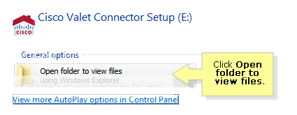
Click Set up your Cisco Valet Connector. Proceed to Step 4.
If you do not see this, click Open folder to view files.

NOTE: For ease of use, the Valet Connector comes preloaded with its installation software. The installation files are stored on the Valet Connector's built in flash storage. However, once Cisco Connect has been successfully installed, this storage facility will no longer be accessible.
Step 3:
Double-click the setup screen as seen in the below image.
NOTE: For Windows XP, the file may be known as Setup.exe. You are not advised to delete any of the files within the AM10. The adapter is not recommended to be used as a USB flash drive.
Step 4:
Read the License Agreement and click Next.
The following screen appears. Wait a few moments while the setup software is setting up your Valet Connector.
Step 6:
If you have an Easy Setup key, select Yes, I have an Easy Setup Key and click Next. Proceed to Step 9.
Otherwise, select No, I don't have an Easy Setup Key and click Next. Proceed to Step 7.
Step 7:
Select your wireless network and click Next.
Step 8:
If prompted, enter the wireless password for your network. Proceed to Step 10.

Step 9:
Follow the on-screen instructions. Click Next once you have completed the on-screen instructions.
Step 10:
The installation is complete when you see the following screen. Click OK.

Step 11:
You are directed to the Cisco Connect screen. Click Close to exit.
Saturday, October 23, 2010
Get back your Dead or not responding Router
Seize The Moment With TFTP
You can use the TFTP (Trivial File Transfer Protocol (define)) command-line utility to upload fresh firmware to the router in its brief moment of wakefulness. Windows, OS X and Linux all include TFTP clients.
First, you need a .bin file containing the known good firmware. You can visit the Linksys site as described above and download the .zip version of the firmware, which includes the .bin file. You can even use a .bin file for an open source firmware, so long as you choose one that's stable and tested and is the correct version for your router (or else you start this whole process all over again).
Windows users need some dexterity here. First, remove power from your router. Open two command prompt windows. In one, you will set up your TFTP command.
Type (but do not yet press enter):
tftp –i 192.168.1.1 PUT firmwarefile.bin
In the second command prompt, enter:
ping –t 192.168.1.1
Run the ping command, which will begin probing and failing to reach the router. Now change window focus to your TFTP command.
Apply power to the router. Watch the ping window for a response, then hit enter in the TFTP window!
Miss by a beat and you’re too late – the pings will fail and your moment has passed. Cut power to the router and repeat the process. You need to start the TFTP the moment you see a successful ping.
For OS X and Linux users, the principle is the same, but the process is easier. First, remove power from your router. Open a terminal window and enter the commands:
tftp 192.168.1.1
binary
rexmt 1
timeout 60
trace
tftp> put firmwarefile.bin
Now apply power to your router. The tftp client will continuously retry uploading the firmware until the router responds. Hopefully, the router will briefly awaken, allowing the firmware upgrade to be sent. About two minutes later, the router will reset and become operational with the new firmware.
If your router simply refuses ever to respond to a ping at 192.168.1.1 despite all these tricks, things are looking grim. You might want to start saving up $60 worth of router replacement kitty.
Short Circuits
You’re desperate. Nothing has worked, and your router is probably a doorstop. At this point, you might want to consider cracking the lid. This will certainly void your warranty, but then again, whatever bricked it this badly probably already did that.
There remains a small glimmer of hope. That glimmer is actually a spark, which, if you’re feeling brave, is what you may need to create.
Two invasive methods of short-circuiting your router have been reported successful. These techniques are controversial. Some in the router modifying community are opposed to even discussing these techniques. We’re not here to judge, nor do we endorse them. If you err even slightly, you’ll probably permanently destroy the router and possibly create a small fire hazard. Take precautions. Rubber-soled shoes and a fire extinguisher, minimum.
Unplug your router. Disassemble the case. On many models of WRT, the case is not held together with screws. You can press down on the top front to pop off the face. Manually untwist the two antennas. Press down on the bottom rear to pop off the backplane. You should be left with a tiny “I paid $60 for this?” circuit board attached to a plastic bottom panel. (Note that some router models do include a couple of screws which are accessible under the rubber feet.)
Look for the flash chip, which is typically marked “Intel” and is toward the front of the circuit board where the LEDs are. The pins on this chip are numbered at the corners – 1, 24, 25, and 48. Small white triangles mark every 5 pins.
The two most successful “shortcuts” have been on routers of V4 or less, using one of two methods: short pins 15 and 16, or short pin 16 to earth via the left antenna input. [At least one reader wrote to tell us that on the WRT54GL v1.1, he had to use pins 16 and 17. Your mileage my vary, kids.]
A small jeweler’s screwdrivers or the tip of a multimeter can be used to short pins 15 and 16. First, apply power to the router and depress the reset button for 30 seconds. Cycle the power again. Short pins 15 and 16, and depress the reset button for another 30 seconds. Now try to ping the router. Many report success.
Alternatively, use a copper or other conductive wire to connect the block of the left antenna input (the one with the braided cable) to pin 16. Again, press the reset button for 30 seconds, press the wire to pin 16 and the antenna block, and press the reset button for another 30 seconds.
You may experience small sparks with these procedures. And you need steady, accurate fingers – the pins on the flash chip are very, very small.
If you miss the correct pins, you’ve probably just completed what is known as “the final nail in the coffin.”
Secrets of the JTAG, aka Time to Buy a New Router
If you research bricked routers at all, you’ll inevitably come across the so-called miracle cure known as the JTAG (short for Joint Test Action Group, which is all about testing circuits). With the JTAG, you can supposedly revive nearly any dead router, not to mention the fact that (apparently) it slices, dices, chops and purees.
However, the JTAG is complicated. You need to build or buy a special cable. It may involve soldering. It connects your PC’s parallel port to circuitry inside your router. It is a very slow communications channel and can take hours of time from beginning to end. And it still may not work, despite the claims.
The JTAG poses the question, how much of a hacker are you? If the idea of building your own cable and connecting it to the guts of the router sounds incredibly cool, then by all means follow this link to the Google search for “hairydairymaid jtag” and follow the results. Otherwise, this may be the time to accept your loss and proceed through the stages of grief: anger, acceptance, and buying a new router.
Page 1 Page 2 Page 3
How to Repair a Dead Linksys Wireless Router Page 2
It’s Dead, Jim!
Despite best — or not-so-best — efforts, accidents happen. Maybe your flash upgrade failed, or your router’s memory became corrupted. You may have made a mistake somewhere in the process. It could have been buggy firmware itself. After all, these open source replacements come with no guarantees. The time for blame has passed.
You’ll know your router has been bricked because, well, it no longer works. More specifically, you will probably see the power light blinking steadily. You may see most of its other lights lit solid.
If your router has a “DMZ” (define) light, note whether it is lit at power on or whether it lights a few seconds later, or never at all. This information could be useful soon.
Sometimes you can breathe new life into your bricked router. It is difficult to say exactly how often bricked routers are successfully revived, but it happens often enough that a number of resurrection techniques have emerged. There is no guarantee, of course, that any of these will work.
The methods devised by the networking community basically fall into two categories: gentle and desperate.
The more popular gentle recovery techniques involve establishing basic network communications with your router through software, followed by reflashing back to known, good firmware.
The desperate recovery techniques involve opening your router and attempting to physically reset its circuitry.
Gentle Recoveries
If you could simply reflash your seemingly dead router with an official Linksys firmware, you could, like Cher, turn back time. Not surprisingly, this is Linksys’ approved recovery method for Windows users, and the only one that won’t void your warranty – if it works.
To test if your router is only “a little bit dead,” you need to see if it responds to pings. First, reset your router to its factory default settings. Do this by powering it on and depressing the reset button for at least 30 seconds. You need the tip of a pen, or better yet, the pointy end of a pen cap to keep the recessed button depressed. The router’s lights will cycle off and back on after it reboots itself.
Using a computer with a wired Ethernet connection to one of the router’s LAN ports, open a command prompt in Windows (go to the Run command in the Windows Start menu, type "cmd" and then hit Enter). Use the ping command to see if the router responds at its factory default IP address, 192.168.1.1.
>ping 192.168.1.1
Pinging 192.168.1.1 with 32 bytes of data:
Reply from 192.168.1.1: bytes=32 time<10ms TTL=128
Reply from 192.168.1.1: bytes=32 time<10ms TTL=128
If you see something like the above, your router is not really dead. You may now dance a happy jig.
If, instead of “Reply from” you see “Request Timed Out” or “Hardware Error” or “Destination host unreachable,” your router is not responding. Do not dance a happy jig, and don’t bother with the rest of this Linksys-approved recovery, because you’ll just be wasting your time. Jump to the next section.
To proceed with the Linksys recovery, visit their Web site to download the latest official firmware. Select your router model from the drop-down list. Be sure to choose the exact model number marked on the underside label of your router – the WRT54G, for example, comes in versions from V1 to V6 (if unmarked, you have a V1).
Click the “Firmware” icon and proceed to download the firmware executable (.exe) file (define).
Force your network adapter into 10Mbps half-duplex mode. Because the procedure varies on different Windows versions, consult this Linksys support page for step-by-step instructions.
Launch the executable file you downloaded. Click “Next” on the splash screen. Set the “Router’s IP Address” to 192.168.1.1 and the “Router’s Password” to admin. Click “Next” again, and the firmware upload process begins.
About two minutes later, the update will complete, the router will reboot, and you’re back in business. At this point, you may revisit upgrading the firmware to an open-source replacement, but be sure to consider what may have gone wrong before, so as not to simply repeat your router’s near-death experience.
The Ping, Dear God, I Beg Of You Technique
If you router did not respond to pings at 192.168.1.1, it isn’t in great shape. But all hope is not yet lost.
Earlier, did you notice if the “DMZ” light on the front panel glows a few seconds after applying power? If yes, you may be able to reset the router to a failsafe mode. Cycle the power to your router and, as soon as DMZ lights up, depress the reset button for two seconds. It may take some coordination to pull this off accurately. Try again to ping the router.
If your firmware is truly hosed, your router may only respond to pings at 192.168.1.1 for a very brief window upon power-up. The moment power is applied, the router hasn’t yet loaded its firmware and is operating on a kind of BIOS. It is during this fleeting moment that you may be able to “catch” the router while still momentarily conscious, just before its brain-dead firmware is loaded.
You need to test whether your router is indeed responsive, even if just for a second, because that is all that's needed to breathe new life into it.
First, connect both your computer and your router to a hub (define) or switch (obviously, the switch built into the router doesn't count). If your computer is wired directly to your router, your Ethernet link may drop when the router is non-responsive, and you could miss the brief moment when it blinks its eyes awake. The hub/switch will keep your link up.
Second, manually configure your wired network settings. Assign your computer the IP address 192.168.1.10 (the last digit should be any number greater than 1), with subnet mask 255.255.255.0, and gateway 192.168.1.1.
Third, open a command prompt in Windows, or a terminal in MacOS X or Linux. Windows users should type:
ping –t 192.168.1.1
The “-t” switch in Windows will keep the ping running indefinitely.
MacOS X or Linux users should type:
ping 192.168.1.1
Your computer will continuously lob pings at the router. Now, cycle power to the router. You’re looking for any sign of life at all – does the router respond to any ping? Depending on your ping command, a successful reply may say “Reply from…” or “XYZ bytes from…” along with information like “time” and “TTL”.
If you do see even one or two replies, you’re set! This verifies that your router experiences a moment of consciousness.
If your router does not respond to a ping within a few seconds of powering up, it isn’t going to happen.
Page1 Page2 Page3
How to Resurrect a Dead Linksys WRT54G Router Part1
One of the more exciting developments for networking enthusiasts has been the evolution of open-source firmware replacements for certain popular, inexpensive routers (usually the famed Linux-running Linksys WRT54G).
While replacement firmware offers the promise of significantly expanded features, greater customization and mondo-tweakability, it also carries some risk. Should misfortune strike, you might, oh, let’s say, render your router into a useless hunk of plastic. Or, as victims prefer to say, you could “brick it.” How does a router become a brick? And if it does, is there any hope of bringing it back to life?
The short answers: "by accident," and "yes... sometimes."
How a Router Becomes a Brick
Bricks are very good at holding up the walls of your house. Bricks are not very good at routing network traffic. You don’t want your router to suddenly become one. (Likewise, you don’t want the bricks in your walls to suddenly become routers – although that would be pretty cool, no?) But sometimes it happens. Often, you can avoid this fate by understanding how a router can become a brick.
There is an alchemy to turning a router into a brick. The most common formula is the bad flash. When you upgrade the firmware in your router, you’re basically swapping in a new brain in place of the old. This brain controls most of the router's cognitive functions.
The upgrade process, described in The Open Source WRT54G Story, can require up to two minutes. If "Something Bad" happens during this process – loss of power to the router, loss of network connectivity to the uploading PC – you may have just bricked your router.
When upgrading your firmware, try to prevent "Something Bad" from happening:
•Be sure the power source is secure.
•Only upgrade through a wired Ethernet connection; do not use a wireless connection.
•Be sure to manually configure the IP address on your uploading PC – do not rely on automatic DHCP address assignment.
•Be sure to disable any software firewall running on your uploading PC, including the Windows firewall.
RAM, Corrupted
Your router has a small amount of on-board NVRAM (define), or non-volatile memory. Sometimes your flash upgrade will be successful, but your NVRAM will become corrupted. Often, this happens when the firmware you uploaded to the router wasn’t exactly the right version for your model. Be sure to read the upgrade instructions for your chosen firmware very, very, very carefully.
For example, consider DD-WRT, one of the most popular open source firmware replacements for Linksys WRT series routers. DD-WRT is available in many flavors. There is a “minimal” build with only a base feature set. There is also a “generic” build which lacks optimizations, and some model-specific builds, among other variants.
When upgrading the router from the Linksys-branded firmware, you are supposed to “step up” by first installing the minimal DD-WRT build, and upgrading from there to a more feature-rich build.
However, when upgrading your router through DD-WRT’s Web interface, you're directed to use the generic build.
Trip up on one of these finer points, and your upgrade may appear successful at first. But then you configure the router, it reboots, and hello Brickville, city of bricks. Most likely, your “successful” flash upgrade produced corrupted NVRAM.
You will always find message board threads by those who have disobeyed the upgrade instructions without dire consequences. These people can also eat pizza for three meals daily and never gain weight, and smoke a pack a day until they’re 98 years old. In fact, they often smoke and eat pizza while upgrading their routers. But the rest of us – we're not like them. Just follow the instructions, carefully.
Page 1 Page2 Page 3
Router Recover from a bad flash or Dead like wrt54g, wrt54gl ...
Recover back your Routers like wrt54g, wrt54gl and many other Router
So, you're afraid you've bricked your router. Don't worry, there are a number of things you can try to get your router working again before giving up and living with the fact that your router is now a paperweight.
It is also unfortunately possible to configure your router in ways which make it dead to the world. These techniques may be useful in these cases also.
Before you continue below, make sure you've first tried a hard reset to revive your router:
1.Disconnect the router from UTP cables (not the power cable).
2.Push reset button for 30 secs.
3.Without releasing reset button, disconnect power cord.
4.Hold the reset button for another 30 secs.
5.Replug the power cord.
6.Still hold the reset button for another 30 secs.
7.Release the reset button and give the router about 10 secs to resettle.
8.Disconnect power cord for another 10 secs and then reconnect.
9.All should be in default settings now.
This procedure is usually called 30/30/30 reset.
If the power light blinks in a neverending way, the 30/30/30 reset has no effect. Go to the Windows section of this page to see the reset-from-scratch procedure
For more help in detail visit my other blog and http://www.dd-wrt.com/wiki/index.php/Recover_from_a_Bad_Flash
Dual Wan DHCP Tomato with Round Robbin Loadbalancing
TODO
* Implement QOS on WAN2 (help?)
* WAN Failover
* DNS Failover (server doesn't appear to switch when an interface is down.)
* VPN testing
Change Log
ver. 0.1 - Modified w2.evt script to account for DNS route and disabled interfaces.
ver. 0.5 - Added iptables rules to preserve routes across connections, saved previous settings to properly remove rules/routes.
Useful info:
"RTNETLINK answers: No such process" means ip route cant find the interface "RTNETLINK answers: file exists" means there is already an overlapping entry in the routing table
I use the following at the beginning of my scripts to paste them into putty:
scrName=fullPathToYourScript
echo "" > $scrName
vi $scrName
:set noautoindent
i
Then just type: `Esc` :wq `Enter`
Preface
I have been working on a dual wan setup for Tomato for a while now and have compiled and modified a few scripts from various sources. This setup enables a second wan on port 4 of the router configured for DHCP (PPPOE is possible with modifications to the script). QOS is only applied to the primary WAN (i.e. WAN2 no QOS). I haven't tested to see what effect port forwarding has as that has not been a priority of the project. This works on a Asus WL-500GPv2 running the following flavor of Tomato:
* tomato-K26USB-1.27.9047MIPSR1-beta16-Ext
available from: http://tomatousb.org/ (Thank you teddy_bear.)
Of course you are modifying your router so the standard disclaimer applies... it is possible you can brick your router, use at your own risk, however I haven't bricked one beyond recovery...yet. I recommend running the w2.init script from the command line first, before you add any lines to the Administration, Scripts web interface, this way a simple power cycle will restore the routing table and firewall if you run into problems, if you mess up the nvram port settings then look into router reset / recovery, unless of course you implemented the safeguard mentioned in the Removal section.
This is a multi step process where first the new interface is created and then scripts are added to the 'Firewall' and 'WAN Up' scripts. Since the firewall and routing table is flushed and rebuilt every time the WAN comes up.
Prerequisites
* 2 wan connections
* jffs enabled and formatted.
* open port 4 on the router for wan 2 (you can change this)
* wan 1 is connected to WAN port
* Console access to router (ssh, telnet, etc...)
Removal
(This is first just in case...)
■as a safety precaution you may want to put this into the 12 second plus button script in case something goes wrong.
Remove the w2.init and w2.evt scripts from Firewall and WAN Up respectively and run the following in a console:
nvram set vlan0ports="0 1 2 3 5*"
nvram set vlan1ports="4 5"
nvram unset vlan2ports
nvram unset vlan2hwname
nvram unset wan2_iface
nvram unset wan_weight
nvram unset wan2_weight
#the following is optional and will remove all scripts from the Firewall and WAN Up... you are warned.
nvram set script_fire=""
nvram set script_wanup=""
# or if you stored your scripts as illustrated this will preserve your other scripts... I like this one better
nvram set script_fire=`nvram get script_fire
grep -v jffs/wan2/w2.evt`
nvram set script_wanup=`nvram get script_wanup
grep -v /jffs/wan2/w2.init`
nvram commit
#for completeness delete the scripts folder
rm -r /jffs/wan2
Setup Dual Wan Round Robbin Loadbalancing
First Create your 2nd wan interface: vlan2 on port 4
■Ports are labeled in reverse order i.e.
Box label: WAN 1 2 3 4
Nvram label: 4 3 2 1 0
some of the newer routers may have different internal assignments, so you may want to run
nvram show
grep vlan.ports
and examine the output... before modification mine looks like:
vlan0ports=1 2 3 4 5*
vlan1ports=0 5
Using the console:
nvram set vlan0ports="3 2 1 5*"
nvram set vlan1ports="4 5"
nvram set vlan2ports="0 5"
nvram set vlan2hwname=et0
nvram set wan2_iface=vlan2
#the following adjust the Round Robbin weighting of each respective interface
nvram set wan_weight=1
nvram set wan2_weight=1
nvram commit
mkdir /jffs/wan2
Using the console and your favorite text editor create the following script and save it to:
/jffs/wan2/w2.init
#!/bin/sh
# script to bring up the secondary wan interface
ModName="WAN2 init: "
runscr="/jffs/wan2/w2.evt"
iface=`nvram get wan2_iface`
lanhost=`nvram get lan_hostname`
#logger $ModName killing old: `ps
grep $iface
grep -v grep
awk '{print $1}'`
kill `ps
grep $iface
grep -v grep
awk '{print $1}'`
ifconfig $iface down
sleep 5
logger $ModName starting... $iface
ifconfig $iface up
ip=`udhcpc -i $iface -s $runscr -H $lanhost
grep Lease
awk '{print $3}'`
#ifconfig $iface up $ip
logger $ModName complete: $iface $ip
Using the console and your favorite text editor create the following script and save it to:
/jffs/wan2/w2.evt
#!/bin/sh
# Dual Wan Script for Tomato
# Purpose: insert the firewall and route entries, update DNS for wan2
# ver. 0.5
# secondary wan comes up, or the firewall is rebuilt
# Assumptions:
# Wan 2 is DHCP
# the following entries exist in nvram and are configured properly ( name(default value) ):
# lan_ifname(br0)
# wan_iface(vlan1)
# wan2_iface(vlan2)
#
# *use these values to adjust the round robbin weighting for each wan:
# wan_weight(1)
# wan2_weight(1)
#
# vlan0ports(3 2 1 5*)
# vlan1ports(4 5)
# vlan2ports(0 5)
# vlan2hwname(et0)
#IF0= local interface
#P0_NET= local network
#IFx= name of the interface on WANx
#IPx= IP address associated with $IFx
#Px= be the IP address of the gateway at Provider x
#Px_NET= be the IP network $Px is in
#IFx_W= Weight to assign the interface #IFx for round robbin load balancing
# Example values for variables:
# Local lan: (this is for understanding only as most values are set using either nvram or dynamically determined)
#IF0=br0
#IP0=192.168.108.1
#P0_NET=192.168.108.0/24
# Wan #1: (this is for understanding only as most values are set using either nvram or dynamically determined)
#IF1=vlan1
#IF1_W=1
#IP1=192.168.8.115
#P1=192.168.8.1
#P1_NET=192.168.8.0/24
# Wan #2: (this is for understanding only as most values are set using either nvram or dynamically determined)
#IF2=vlan2
#IF2_W=1
#IP2=192.168.0.14
#P2=192.168.0.1
#P2_NET=192.168.0.0/24
# dnamasq DNS table path
RESOLV_CONF="/tmp/etc/resolv.dnsmasq"
WANname="WAN2 evt: "
#must use numbers for table names
T1=100
T2=200
# marks for rules/routes
Mrk1=0x100
Mrk2=0x200
#logger $WANname start $0 $1
case "$1" in
deconfig)
ifconfig $interface 0.0.0.0
nvram set wan2_get_dns=""
;;
renew
bound)
ifconfig $interface $ip
${broadcast:+broadcast $broadcast}
${subnet:+netmask $subnet}
if [ -n "$router" ] ; then
#echo "deleting routers"
#while route del default gw 0.0.0.0 dev $interface ; do
# :
#done
# record the gateway
for i in $router ; do
#route add default gw $i dev $interface
#logger $WANname gateway $i
nvram set wan2_gateway=$i
done
fi
# i don't think I want to lose my existing dns servers.
${domain:+echo search $domain >> $RESOLV_CONF}
for i in $dns ; do
grep $i $RESOLV_CONF
if [ $? -ne 0 ]; then
logger $WANname adding dns $i
echo nameserver $i >> $RESOLV_CONF
nvram set wan2_get_dns=$i
fi
#if you use dyndns you may wan to use this.
#wget -O /dev/null http://USER:PASSWORD@members.dyndns.org/nic/update?hostname=DOMAIN
done
;;
esac
#logger $WANname variable init
# retrieve all the old settings to use for iptables/route removal
IF0=`nvram get lan_ifname_old`
IP0=`nvram get lan_ip_old`
P0_NET=`nvram get lan_net_old`
IF1=`nvram get wan_iface_old`
IP1=`nvram get wan_ip_old`
P1=`nvram get wan_gateway_old`
P1_NET=`nvram get wan_net_old`
IF1_W=`nvram get wan_weight_old`
IF2=`nvram get wan2_iface_old`
IP2=`nvram get wan2_ip_old`
P2=`nvram get wan2_gateway_old`
P2_NET=`nvram get wan2_net_old`
IF2_W=`nvram get wan2_weight_old`
IF2_DNS=`nvram get wan2_get_dns_old`
# since we want to preserve the existing routing table
# just remove what we are going to add
#logger $WANname removing firewall and routes
ip route del default scope global nexthop via $P1 dev $IF1 weight $IF1_W nexthop via $P2 dev $IF2 weight $IF2_W
#ip route del $P1_NET dev $IF1 src $IP1 table $T1
#ip route del default via $P1 table $T1
#ip route del $P2_NET dev $IF2 src $IP2 table $T2
#ip route del default via $P2 table $T2
ip route del $P1_NET dev $IF1 src $IP1
ip route del $P2_NET dev $IF2 src $IP2
ip route del default via $P1
ip route del default via $P2
ip route flush table $T1
ip route flush table $T2
ip rule flush
ip rule add lookup main prio 32766
ip rule add lookup default prio 32767
#logger $WANname routes removed
# remove iptables rules
iptables -D FORWARD $NDX -o $IF2 -j wanout
iptables -D FORWARD $NDX -i $IF2 -j wanin
iptables -D INPUT -j DROP -i $IF0 -d $IP2
iptables -t nat -D PREROUTING -j DROP -i $IF2 -d $P0_NET
iptables -t nat -D PREROUTING -j DNAT -p icmp -d $P2 --to-destination $IP0
iptables -t mangle -D PREROUTING -i $IF1 -m state --state NEW -j CONNMARK --set-mark $Mrk1
iptables -t mangle -D PREROUTING -i $IF2 -m state --state NEW -j CONNMARK --set-mark $Mrk2
iptables -t mangle -D POSTROUTING -o $IF1 -m state --state NEW -j CONNMARK --set-mark $Mrk1
iptables -t mangle -D POSTROUTING -o $IF2 -m state --state NEW -j CONNMARK --set-mark $Mrk2
iptables -t mangle -D PREROUTING -i $IF0 -m state --state ESTABLISHED,RELATED -j CONNMARK --restore-mark
iptables -t mangle -D OUTPUT -m state --state ESTABLISHED,RELATED -j CONNMARK --restore-mark
iptables -D POSTROUTING -t nat -m mark --mark $Mrk1 -j SNAT --to-source $IP1
iptables -D POSTROUTING -t nat -m mark --mark $Mrk2 -j SNAT --to-source $IP2
iptables -t nat -D POSTROUTING -j MASQUERADE -o $IF2
#logger firewall rules removed
# Fill Local lan variables
IF0=`nvram get lan_ifname`
IP0=`ifconfig $IF0
grep -Eo '[0-9]{1,3}\.[0-9]{1,3}\.[0-9]{1,3}\.[0-9]{1,3}'
awk -F . '$1 != 127 && $1 !=255 && $4 < 255{print $1 "." $2 "." $3 "." $4}'`
P0_NET=`echo $IP0
grep -Eo '[0-9]{1,3}\.[0-9]{1,3}\.[0-9]{1,3}\.[0-9]{1,3}'
awk -F . '$1 != 127 && $1 !=255 && $4 < 255{print $1 "." $2 "." $3 ".0/24"}'`
# Fill Wan #1 variables
IF1=`nvram get wan_iface`
IP1=`ifconfig $IF1
grep -Eo '[0-9]{1,3}\.[0-9]{1,3}\.[0-9]{1,3}\.[0-9]{1,3}'
awk -F . '$1 != 127 && $1 !=255 && $4 < 255{print $1 "." $2 "." $3 "." $4}'`
P1=`nvram get wan_gateway`
P1_NET=`echo $IP1
grep -Eo '[0-9]{1,3}\.[0-9]{1,3}\.[0-9]{1,3}\.[0-9]{1,3}'
awk -F . '$1 != 127 && $1 !=255 && $4 < 255{print $1 "." $2 "." $3 ".0/24"}'`
IF1_W=`nvram get wan_weight`
# Fill Wan #2 variables
IF2=`nvram get wan2_iface`
IP2=`ifconfig $IF2
grep -Eo '[0-9]{1,3}\.[0-9]{1,3}\.[0-9]{1,3}\.[0-9]{1,3}'
awk -F . '$1 != 127 && $1 !=255 && $4 < 255{print $1 "." $2 "." $3 "." $4}'`
P2=`nvram get wan2_gateway`
P2_NET=`echo $IP2
grep -Eo '[0-9]{1,3}\.[0-9]{1,3}\.[0-9]{1,3}\.[0-9]{1,3}'
awk -F . '$1 != 127 && $1 !=255 && $4 < 255{print $1 "." $2 "." $3 ".0/24"}'`
IF2_W=`nvram get wan2_weight`
IF2_DNS=`nvram get wan2_get_dns`
# add the routes and firewall rules
if [ "$1" != "deconfig" ]; then
#logger $WANname appending firewall and routes
if [ "$IF2_DNS" != "" ]; then
#Add the wan2 dns route if it exists
nvram set wan2_get_dns_old=$IF2_DNS
nvram set wan2_iface_old=$IF2
ip route add $IF2_DNS dev $IF2
fi
if [ "$IP1" != "" ]; then
nvram set wan_iface_old=$IF1
nvram set wan_ip_old=$IP1
nvram set wan_gateway_old=$P1
nvram set wan_net_old=$P1_NET
nvram set wan_weight_old=$IF1_W
# add rules first
ip rule add from $IP1 table $T1 prio 100
ip rule add fwmark $Mrk1 table $T1 prio 101
# now add the routes...
ip route add $P1_NET dev $IF1 src $IP1 table $T1
ip route add $P1_NET dev $IF1 src $IP1
ip route add default via $P1 table $T1
ip route add $P0_NET dev $IF0 table $T1
ip route add 127.0.0.0/8 dev lo table $T1
fi
if [ "$IP2" != "" ]; then
# save values
nvram set wan2_iface_old=$IF2
nvram set wan2_ip_old=$IP2
nvram set wan2_gateway_old=$P2
nvram set wan2_net_old=$P2_NET
nvram set wan2_weight_old=$IF2_W
# add rules first
ip rule add from $IP2 table $T2 prio 200
ip rule add fwmark $Mrk2 table $T2 prio 201
# now add the routes...
ip route add $P2_NET dev $IF2 src $IP2 table $T2
ip route add $P2_NET dev $IF2 src $IP2
ip route add default via $P2 table $T2
ip route add $P0_NET dev $IF0 table $T2
ip route add 127.0.0.0/8 dev lo table $T2
fi
# if both interfaces are up load balance
if [[ "$IP1" != "" && "$IP2" != "" ]]; then
logger $WANname LoadBalance enabled
ip route add $P2_NET dev $IF2 table $T1
ip route add $P1_NET dev $IF1 table $T2
# now apply weighted round robbin load balancing:
ip route add default scope global nexthop via $P1 dev $IF1 weight $IF1_W nexthop via $P2 dev $IF2 weight $IF2_W
else
# see if we can add a default route
if [ "$IP1" != "" ]; then
logger $WANname LoadBalance disabled Default route via $IF1
ip route add default via $P1
fi
if [ "$IP2" != "" ]; then
logger $WANname LoadBalance disabled Default route via $IF2
ip route add default via $P2
fi
fi
ip route flush cache
if [ "$IP2" != "" ]; then
#get the line number after wanout to insert the interface at the correct position
NDX=`iptables -L FORWARD -v --line-numbers
sed -n "/wanout/h;$ {x;p;}"
awk '{print $1}'`
NDX=`expr $NDX + 1`
iptables -I FORWARD $NDX -o $IF2 -j wanout
iptables -I FORWARD $NDX -i $IF2 -j wanin
iptables -I INPUT -j DROP -i $IF0 -d $IP2
iptables -t nat -A PREROUTING -j DROP -i $IF2 -d $P0_NET
iptables -t nat -A PREROUTING -j DNAT -p icmp -d $P2 --to-destination $IP0
# Setup rules for preserving routes across connections (conversations)
iptables -t mangle -A PREROUTING -m state --state ESTABLISHED,RELATED -j CONNMARK --restore-mark
iptables -t mangle -A OUTPUT -m state --state ESTABLISHED,RELATED -j CONNMARK --restore-mark
iptables -t mangle -A PREROUTING -i $IF1 -m state --state NEW -j CONNMARK --set-mark $Mrk1
iptables -t mangle -A PREROUTING -i $IF2 -m state --state NEW -j CONNMARK --set-mark $Mrk2
iptables -t mangle -A PREROUTING -m connmark --mark $Mrk1 -j MARK --set-mark $Mrk1
iptables -t mangle -A PREROUTING -m connmark --mark $Mrk2 -j MARK --set-mark $Mrk2
iptables -t mangle -A PREROUTING -m state --state NEW -m connmark ! --mark 0 -j CONNMARK --save-mark
# Selective routing example: send all http traffic to a specific interface (WAN 1)
#iptables -t mangle -A PREROUTING -i $IF1 -m state --state NEW -p tcp --dport 80 -j CONNMARK --set-mark $Mrk1
#iptables -t mangle -A PREROUTING -i $IF1 -m state --state NEW -p tcp --dport 443 -j CONNMARK --set-mark $Mrk1
# enable masquerading on the interface
iptables -t nat -A POSTROUTING -j MASQUERADE -o $IF2
# turn off Reverse Path Filtering as this is a multi-homed router.
RP_PATH=/proc/sys/net/ipv4/conf
for IFACE in `ls $RP_PATH`; do
echo 0 > $RP_PATH/$IFACE/rp_filter
done
fi
fi
When testing out the scripts a bunch of "RTNETLINK answers" may occur as the script is trying to remove routes that don't yet exist, this is ok. Once you have tested out your connection using the console add the following to the Firewall and WAN Up scripts and your done.
Web Interface:Administration:Scripts:Firewall
/jffs/wan2/w2.evt
Web Interface:Administration:Scripts:WAN Up
/jffs/wan2/w2.init
Failover Script
#!/bin/sh
# Failover Script for dual wan.
# ver. 0.1
# 0 is good
# !0 bad
#IFx_PINGIP=the address to ping
#IFx= the interface name
#IFx_IP= the interface IP
#IFx_GW= the gateway associated with the interface
#IFx_FAIL_MAX= the trigger point at which the interface is considered down
#IFx_SUCC_MAX= the trigger point at which the interface is considered up
#IFx_W= round robbin weighting factor
#IFx_PING_CT= the current test ping tally
#IFx_PING= the current ping result
#IFx_LPING= the previous ping result
#IFx_ISUP= the status of the interface as determined by the MAX ping counts
#IFx_TEST= testing status
# WAN 1 tracking variables
IF1_PING_CT=0
IF1_PING=1
IF1_LPING=-3
IF1_ISUP=1
IF1_TEST=0
# WAN 2 tracking variables
IF2_PING_CT=0
IF2_PING=1
IF2_LPING=-3
IF2_ISUP=1
IF2_TEST=0
#apply defaults if needed
if [ `nvram get wanfail_defaults` != "1" ]; then
echo setting nvram defaults
nvram set wanfail_defaults=1
nvram set wanfail_interval=10
nvram set wanfail_ping_timeout=2
nvram set wanfail_w1_pingadd=www.yahoo.com
nvram set wanfail_w1_fail_max=5
nvram set wanfail_w1_succ_max=2
nvram set wanfail_w1_refresh=1
nvram set wanfail_w2_pingadd=www.yahoo.com
nvram set wanfail_w2_fail_max=5
nvram set wanfail_w2_succ_max=2
nvram set wanfail_w2_refresh=1
fi
# interval to pause between ping attempts
SLEEP_SEC=`nvram get wanfail_interval`
# ping timeout
PING_SEC=`nvram get wanfail_ping_timeout`
PING_DLY=2
#run the configuration the first time.
nvram set wanfail_w1_refresh=0
nvram set wanfail_w2_refresh=0
EXECFG=0
while : ; do
echo " "
echo " "
echo sleeping for $SLEEP_SEC sec.
sleep $SLEEP_SEC
echo " "
echo Testing WAN 1
if [ `nvram get wanfail_w1_refresh` != "1" ]; then
echo refreshing wan1 vars
nvram set wanfail_w1_refresh=1
# Obtain Wan #1 variables
IF1_PINGIP=`nvram get wanfail_w1_pingadd`
IF1=`nvram get wan_iface`
IF1_IP=`ifconfig $IF1
grep -Eo '[0-9]{1,3}\.[0-9]{1,3}\.[0-9]{1,3}\.[0-9]{1,3}'
awk -F . '$1 != 127 && $1 !=255 && $4 < 255{print $1 "." $2 "." $3 "." $4}'`
IF1_GW=`nvram get wan_gateway`
IF1_FAIL_MAX=`nvram get wanfail_w1_fail_max`
IF1_SUCC_MAX=`nvram get wanfail_w1_succ_max`
IF1_W=`nvram get wan_weight`
PING_SEC=`nvram get wanfail_ping_timeout`
SLEEP_SEC=`nvram get wanfail_interval`
SLEEP_SEC=`expr $SLEEP_SEC - $PING_DLY`
if [ $SLEEP_SEC -lt 5 ]; then
nvram set wanfail_interval=5
SLEEP_SEC=5
fi
fi
# WAN 1
# ping the test ip
echo ping -W $PING_SEC -I $IF1_IP -c 1 $IF1_PINGIP > /dev/null 2>&1
ping -W $PING_SEC -I $IF1_IP -c 1 $IF1_PINGIP > /dev/null 2>&1
IF1_PING=$?
echo $IF1 Ping result: $IF1_PING
if [ $IF1_PING -ne $IF1_LPING ]; then
# here all we know is the ping status changed so reset the counter.
echo $IF1 Status switched $IF1_LPING to $IF1_PING
IF1_PING_CT=0
IF1_TEST=0
fi
# record the last ping
IF1_LPING=$IF1_PING
# if were in testing then proceed
if [ $IF1_TEST -eq "0" ]; then
if [ $IF1_PING -eq $IF1_ISUP ]; then
# stop testing as the status has not really changed...
echo testing halted as the ping result is consistent with the status... $IF1_PING = $IF1_ISUP
IF1_TEST=1
else
#increment the ping count
IF1_PING_CT=`expr $IF1_PING_CT + 1`
echo $IF1 ping count=$IF1_PING_CT
if [ $IF1_ISUP -eq "0" ]; then
echo testing for failure
# zero equals up so check for failure
# so if we are testing and status is up check to see if we are past the trigger limit
if [ $IF1_PING_CT -gt $IF1_FAIL_MAX ]; then
IF1_TEST=1
IF1_ISUP=1
EXECFG=0
echo $IF1 exceeded the fail count status changed to $IF1_ISUP
fi
else
echo testing for success
# test for max success condition
if [ $IF1_PING_CT -gt $IF1_SUCC_MAX ]; then
#not testing anymore
IF1_TEST=1
IF1_ISUP=0
EXECFG=0
echo $IF1 exceeded the success count status changed to $IF1_ISUP
fi
fi
fi
fi
sleep $PING_DLY
echo " "
echo Testing WAN 3
# WAN 2
if [ `nvram get wanfail_w2_refresh` != "1" ]; then
echo refreshing wan2 vars
nvram set wanfail_w2_refresh=1
# Obtain Wan #2 variables
IF2_PINGIP=`nvram get wanfail_w2_pingadd`
IF2=`nvram get wan2_iface`
IF2_IP=`ifconfig $IF2
grep -Eo '[0-9]{1,3}\.[0-9]{1,3}\.[0-9]{1,3}\.[0-9]{1,3}'
awk -F . '$1 != 127 && $1 !=255 && $4 < 255{print $1 "." $2 "." $3 "." $4}'`
IF2_GW=`nvram get wan2_gateway`
IF2_FAIL_MAX=`nvram get wanfail_w2_fail_max`
IF2_SUCC_MAX=`nvram get wanfail_w2_succ_max`
IF2_W=`nvram get wan2_weight`
PING_SEC=`nvram get wanfail_ping_timeout`
SLEEP_SEC=`nvram get wanfail_interval`
SLEEP_SEC=`expr $SLEEP_SEC - $PING_DLY`
if [ $SLEEP_SEC -lt 5 ]; then
nvram set wanfail_interval=5
SLEEP_SEC=5
fi
fi
# ping the test ip
echo ping -W $PING_SEC -I $IF2_IP -c 1 $IF2_PINGIP > /dev/null 2>&1
ping -W $PING_SEC -I $IF2_IP -c 1 $IF2_PINGIP > /dev/null 2>&1
IF2_PING=$?
echo $IF2 Ping result: $IF2_PING
if [ $IF2_PING -ne $IF2_LPING ]; then
# here all we know is the ping status changed so reset the counter.
echo $IF2 Status switched $IF2_LPING to $IF2_PING
IF2_PING_CT=0
IF2_TEST=0
fi
# record the last ping
IF2_LPING=$IF2_PING
# if were in testing then proceed
if [ $IF2_TEST -eq "0" ]; then
if [ $IF2_PING -eq $IF2_ISUP ]; then
# stop testing as the status has not really changed...
echo testing halted as the ping result is consistent with the status... $IF2_PING = $IF2_ISUP
IF2_TEST=1
else
#increment the ping count
IF2_PING_CT=`expr $IF2_PING_CT + 1`
echo $IF2 ping count=$IF2_PING_CT
if [ $IF2_ISUP -eq "0" ]; then
echo testing for failure
# zero equals up so check for failure
# so if we are testing and status is up check to see if we are past the trigger limit
if [ $IF2_PING_CT -gt $IF2_FAIL_MAX ]; then
IF2_TEST=1
IF2_ISUP=1
EXECFG=0
echo $IF2 exceeded the fail count status changed to $IF2_ISUP
fi
else
echo testing for success
# test for max success condition
if [ $IF2_PING_CT -gt $IF2_SUCC_MAX ]; then
#not testing anymore
IF2_TEST=1
IF2_ISUP=0
EXECFG=0
echo $IF2 exceeded the success count status changed to $IF2_ISUP
fi
fi
fi
fi
echo testing done
if [ $EXECFG -eq "0" ]; then
EXECFG=1
echo configuring routes....
# if both up great
if [[ $IF1_ISUP -eq "0" && $IF2_ISUP -eq "0" ]]; then
# configure for load balancing
echo "ip route replace default scope global nexthop via $IF1_GW dev $IF1 weight $IF1_W nexthop via $IF2_GW dev $IF2 weight $IF2_W"
#ip route replace default scope global nexthop via $IF1_GW dev $IF1 weight $IF1_W nexthop via $IF2_GW dev $IF2 weight $IF2_W
ip route replace default scope global nexthop via $IF1_GW dev $IF1 weight $IF1_W nexthop via $IF2_GW dev $IF2 weight $IF2_W
elif [ $IF1_ISUP -eq "0" ]; then
# set default route for IF1
echo "ip route replace default scope global via $IF1_GW dev $IF1"
ip route replace default scope global via $IF1_GW dev $IF1
# the implication is that the dhcp server may have changed... so bounce it
# $IF2 is down so attempt to get a new dhcp lease as that could have changed.
elif [ $IF2_ISUP -eq "0" ]; then
# set default route for IF2
echo "ip route replace default scope global via $IF2_GW dev $IF2"
ip route replace default scope global via $IF2_GW dev $IF2
# $IF1 is down so attempt to get a new dhcp lease as that could have changed.
else
#both are down...
echo "both are down... game over man! game over!.... we're all gonna die down here!"
# $IF1 is down so attempt to get a new dhcp lease as that could have changed.
# $IF2 is down so attempt to get a new dhcp lease as that could have changed.
fi
fi
done
Friday, April 16, 2010
How to install DD-WRT firmware on Linksys WRT54GL Wireless Router and receive wireless singnal
This tutorial will show you how to install the DD-WRT firmware on a Linksys WRT54GL wireless router. The DD-WRT firmware makes advanced features, usually only available on more expensive routers, available on cheaper models. My purpose for this mod is to create a wireless receiver for my modded Xbox.
Hardware you will need:
Install DD-WRT Version 23 SP2 Mini:
For more Visit Linksys Wireless Router Hack
Hardware you will need:
- Linksys WRT54GL wireless router
- PC
- Ethernet cord
- Internet Explorer
- DD-WRT Version 23 SP2 Mini
- DD-WRT Version 23 SP2 Standard
- Compression application (Winzip, WinRAR, etc.)
**DISCLAIMER** The following instructions will void your warranty and if done incorrectly may brick your router. I can not be held responsible for any resulting equipment failure or otherwise undesirable results. Proceed at your own risk.Linksys Wireless Router Hack ....-.
Install DD-WRT Version 23 SP2 Mini:
- Disable all firewalls, anti-virus software, and wireless connections on the PC
- Unzip the DD-WRT Version 23 SP2 mini and standard compressed files
- Connect the PC to the WRT54GL via Ethernet cable (ports labeled 1-4, not the WAN or Internet port)
- Open Internet Explorer and navigate to 192.168.1.1 (this will open the Linksys web interface)
NOTE: You will be presented with a login prompt, use the credentials you set when configuring the router, if you cannot remember what they are, press the Reset button for 30 seconds, username and password will be reset (username: (blank), password: admin) - Select the Administration->Factory Defaults tab
- Select the Yes radio button in the Restore Factory Defaults: section and press the Save Settings button
- Press the OK button on Warning prompt
- A success screen will appear followed by a login prompt (username: (blank), password: admin)
- Select the Administration->Firmware Upgrade tab
- Press the Browse… button and navigate to the location which the mini version of DD-WRT was unzipped
- Select the dd-wrt.v23_mini_generic.bin file and press the Open button, then the Upgrade button
NOTE: Do NOT do anything on the computer while the upgrade is taking place, a failed upgrade can brick your router - Press the continue button on the success page
- The login prompt will appear again (username: root, password: admin) but login should FAIL
- Verify that the router is working by pinging it (go to Start->Run, type cmd, press Enter, type ping 192.168.1.1, press enter, should be successful)
- If router is working, press and hold the Reset button on the back of the router then unplug the power to the router
- While continuing to hold the Reset button, plug in the power to the router and hold the Reset button for 30 more seconds
- When the Power LED on the router stop blinking, open Internet Explorer and navigate to 192.168.1.1, you may be prompted to login (username: root, password: admin)
- DD-WRT mini web interface should now be displayed
- Repeat steps 1-9 from above
- Press the Browse… button and navigate to the location which the standard version of DD-WRT was unzipped
- Select the dd-wrt.v23_generic.bin file and press the Open button
- Select the Default settings radio button in the After flashing, reset to section, then press the Upgrade button
NOTE: Do NOT do anything on the computer while the upgrade is taking place, a failed upgrade can brick your router - A success page will appear followed by the DD-WRT standard web interface
For more Visit Linksys Wireless Router Hack
You can use wireless router with DD-WRT as a wireless adapter for Xbox free
This tutorial will show you how to use a wireless router with the DD-WRT firmware installed as a wireless router for and Xbox or Xbox 360.
Hardware you will need:
Obtain Host router info:
If you have a modded Xbox running Xbox Media Center (XBMC) connected to the Client router and wish to connect to a shared folder on a PC connected to the Host router, you may have to connect by entering the IP address of the PC sharing the folder rather than browsing to the PC.
For More Visit free Wireless adapter
Freewebpromotion.tk
Hardware you will need:
- Wireless router with DD-WRT firmware installed (Client)
- Wireless router (Host)
- Xbox or Xbox 360
- PC
- Ethernet cord (optional)
- Internet Explorer
Obtain Host router info:
- Connect PC to Host router via Ethernet cord or wirelessly
- Open Internet Explorer and navigate to 192.168.1.1 (this will open the Host router’s web interface)
NOTE: You will be presented with a login prompt, use the credentials you set when configuring the router, if you cannot remember what they are, press the Reset button for 30 seconds, username and password will be reset to factory defaults (username: (blank), password: admin) - Select the Setup->Basic Setup tab and save the Host router’s Local IP, Subnet Mask, and Starting IP Address (usually 192.168.1.1, 255.255.255.0, 192.168.1.100)
- Select the Wireless->Basic Wireless Settings tab and save the router’s SSID
- Select the Wireless->Wireless Security tab and save the security info, if used
- Select the Status->Router tab and save the DNS 1, and DNS 2 values
- Connect PC to Client router via Ethernet cord or wirelessly
- Open Internet Explorer and navigate to 192.168.1.1 (this will open the Host router’s web interface)
NOTE: You will be presented with a login prompt, use the credentials you set when configuring the router, if you cannot remember what they are, press the Reset button for 30 seconds, username and password will be reset to factory defaults (username: root, password: admin) - Select the Wireless->Basic Settings tab
- Change Wireless Mode to Client, change Wireless Network Name (SSID) to value saved from step 4 above, then press the Save Settings button
- Select Wireless->Wireless Security tab
- Enter wireless security settings from step 5 above and press the Save Settings button, if applicable
- Select Setup->Basic Setup tab
- Change Internet Connection Type.Connection Type to Static IP
- Change Internet Connection Type.Internet IP Address to 192.168.1.2 (or any IP between Host’s Local IP (192.168.1.1) and Host’s Staring IP Address (usually 192.168.1.100))
- Change Internet Connection Type.Subnet Mask to value from step 3 above (usually 255.255.255.0)
- Change Internet Connection Type.Gateway to Host router’s Local IP from step 3 above (usually 192.168.1.1)
- Change Internet Connection Type.Static DNS 1 to Host router’s Local IP from step 3 above (usually 192.168.1.1)
- Change Internet Connection Type.Static DNS 2 to DNS 1 value from step 6 above
- Change Internet Connection Type.Static DNS 3 to DNS 2 value from step 6 above
- Change Router IP.Local IP Address to 192.169.2.2
- Change Router IP.Subnet Mask to 255.255.255.0
- Change Router IP.Gateway to 192.168.2.2
- Change Router IP.Local DNS to Host router’s Local IP from step 3 above (usually 192.168.1.1)
- Press the Save Settings button, you will get Settings are successful screen, then press the Close button
- Go to Start->Run, then type cmd, and press Enter
- Type ipconfig /release, then press Enter
- Type ipconfig /renew, then press Enter
- Open Internet Explorer and navigate to 192.168.2.2 to make sure the settings are saved
NOTE: notice the new IP address for the Client router, it will be the value specified in step 15
If you have a modded Xbox running Xbox Media Center (XBMC) connected to the Client router and wish to connect to a shared folder on a PC connected to the Host router, you may have to connect by entering the IP address of the PC sharing the folder rather than browsing to the PC.
For More Visit free Wireless adapter
Freewebpromotion.tk
Subscribe to:
Posts (Atom)